


Product Overview
The Automatic Degassing Constant Pressure Water Refill Device is a new-type water treatment equipment independently developed by our company, adopting internationally advanced technology. It integrates three core functions—constant pressure regulation, automatic water supply, and vacuum degassing—into one, specifically designed for central heating and central air conditioning systems.
This device effectively solves key problems such as unstable system pressure, insufficient water supply, and gas accumulation in closed water systems, ensuring the safe, stable, and efficient operation of the entire system. With advanced PLC control technology, reliable component configuration, and user-friendly operation, it is widely applicable to various closed water circulation scenarios, providing professional and efficient water treatment solutions for industrial and commercial users.
Technical Specifications
Pneumatic Type
Specification and Model
Example: ECH-DY-1-320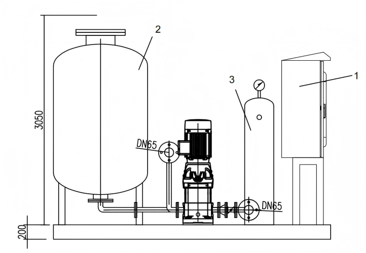
DY - pneumatic diaphragm tank.
1 - supplementary water pump flow range.
320 - diaphragm tank effective volume.
Notes for Selection
System parameters.
System type (e.g. chilled water system).
System water volume. 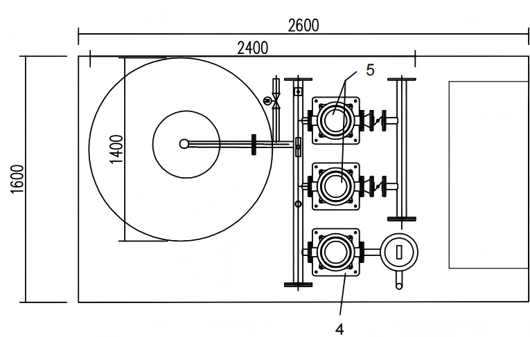
Working pressure (1.0MPa, 1.6MPa, 2.5MPa).
Other parameters required by clients.
Device Configuration
Supplementary water pump flow ≥ 4m/h, and the system adopts variable frequency water supply.
Power supply voltage AC380V
One supplementary water pump in use and one for backup.
| 5 | Make-up pump | Flow rate16m3/h,Head83m(Wilo Pumps) | 2 |
| 4 | Degassing pump | Flow rate2m3/h,Head83m(Wilo Pump) | 1 |
| 3 | Degassing tank | Material:304 Stainless Steel,Design Pressure:1.6 MPa | 1 |
| 2 | Pressure tank Diameter1400mm,Height2950mm,Carbon steel (with built-in butyl rubber diaphragm)Pressure Vessel1.6MPA | 1 | |
| 1 | Control Cabinet | PLC、Touch PanelIP54,Variable frequency adjustable | 1 |
| Item No. | Description | Remarks | Quantity |

The working principle of the comnstan peressure water supply and degassing device is asfollows:
The static pressure of the systemmm is used as the designed initial pressure headwithin the expansion tank, and the pressure required to prevent the hot water in thesystem from vaporizing is used as the operating terminal pressure head withintheexpansion tank. During initial operation, the makeup water pump is first startedtofill the system and the water chamber inside the pressure tank with water. Oncethesystem is filled, excess water is forced into the bladder. Due to theincompressibilityof water, as the water volume continuously increases, the volume ofthe waterchamber also expands, compressing the air chamber and causing thepressureinside the tank to rise. When the pressure reaches the designed pressure,thepressure controller shuts off the makeup water pump.
pressure to rise above the designed pressure, the excess water is dischargedthrough the safety valve back to the makeup water tank for reuse. When the watervolume in the system decreases due to leakage or a drop in temperature, causing thesystem pressure to drop, the water in the bladder is continuously pressed into the pipenetwork to compensate for the pressure drop loss. When the system pressure dropsto the minimum allowable designed pressure, the pressure controller restarts themakeup water pump to supply water to the pipe network and the pressure tank. Thisprocess repeats itself in a cycle
Technical Specifications | ||||||||||
Design Parameters | Design , Manufacturing , and Inspection Standards | |||||||||
Container Type | I | GB150. 1~ 150.4-2024 《 aressure vesses 》 | ||||||||
Work-related stress MPa | 1.6 | |||||||||
Design pressure MPa | 1.6 | Manufacturing and Inspection Requirements | ||||||||
Operating temperature ℃ | 80 | ConnectorType | Unless otherwise specified in the drawing , the types of welded joints shall comply with the provisions of HG20583-2011; the welds between the nozzle , the inner cylinder, and the heads must be fully penetrated, and the fillet dimensions for fillet welds shall be based on the thickness of the thinner plate;Flange welding shall comply with the provisions of the relevant flange standards; all other requirements shall comply with the provisions of GB/T985.1-2008. | |||||||
Design temperature ℃ | 120 | |||||||||
medium | Water, air | |||||||||
Media Properties | Non-toxic, non-explosive | |||||||||
Density of the medium iha 3 | ||||||||||
Material of the primary pressure-bearing component | Q345R | |||||||||
Corrosion allowance | ||||||||||
Weld Joint Coefficient | 0.85/1.0 | Weldingrdd | Welding between XX and XX | Welding rod grade | ||||||
Welding Procedure Specification | NB/T47015-2023 | |||||||||
Coating and Transport Packaging of PressureVessels | NB/T10558-2021 | Non- | Detection rate , methods | Testing Standards | Passing Grade | |||||
Total volume | 3.1 | A | cylinder | RT/20%and no less than 250 mm | NB/T47013.2-2015 | Ⅲ/AB | ||||
Earthquake intensity | / | |||||||||
Soil type at the site | / | End cap | RT/100% | NB/T47013.2-2015 | Ⅱ/AB | |||||
Surface roughness | / | Ear hook | MT/100% | NB/T47013.4-2015 | Ⅰ | |||||
Safety Valve Model | / | Test | Types of Tests | |||||||
Safety valve set pressure | / | Hydraulic test pressure Mpa | 1.6 | |||||||
Insulation thickness | / | Design service life (expected) of pressure vessels | 10 years | |||||||
Maximum lifting capacity | ~285 | Pipe Outlet Location | See the figure below | |||||||
Primary load-bearing component | ||||||||||
Material Name | Material Standards | Delivery condition | Notes | |||||||
Q345R | GB/T713.2-2023 | hot-rolled | Shell and Head | |||||||
20 | GB/T8163-2018 | hot-rolled | nozzle | |||||||
20II | NB/T47008-2017 | normalizing | flange | |||||||
Pipe Fittings | ||||||||||
Symbol | Nominal size | Flange Connection Standards | sealing surface | Purpose or Name | ||||||
a | RP1/2 | / | internal thread | Exhaust valve connection | ||||||
b | M20X1.5 | / | internal thread | Pressure gauge connection | ||||||
c | M10 | / | / | Inflation valve connection | ||||||
d | PN25 DN50 | HG/T20592-2009 | RF | Inlet and outlet | ||||||
Specification selection table (Standard equipment: one for use and one for backup, single diaphragm tank and intelligent control system)
| Model Numbersz | Supplementary water pump flow range (m³/h) | Diaphragm tan Supplementary water pump flow range (m³/h) k effective volume (L) | Size (L*W*H) mm | Connection method of water inlet caliber | Connection method of water supply caliber | Connection method of drainage caliber | Weight (kg) | Applicable floor area (m²) |
| ECH-DY-2-100 | 0.5-2.5 | 200 | 1350*800*1200 | DN50/flange | DN50/flange | DN25/thread | 300 | 7500-23000 |
| ECH-DY-4-200 | 2.5-4.5 | 400 | 1350*800*1200 | DN50/flange | DN50/flange | DN25/thread | 320 | 23000-38000 |
| ECH-DY-6-400 | 4.5-6.5 | 600 | 1350*800*1200 | DN50/flange | DN50/flange | DN25/thread | 350 | 38000-53000 |
| ECH-DY-8-400 | 6.5-8.5 | 600 | 1350*800*1200 | DN50/flange | DN50/flange | DN25/thread | 380 | 53000-68000 |
| ECH-DY-10-600 | 8.5-10.5 | 800 | 1550*950*1800 | DN50/flange | DN50/flange | DN25/thread | 500 | 68000-83000 |
| ECH-DY-12-600 | 10.5-12.5 | 800 | 1550*950*1800 | DN50/flange | DN50/flange | DN25/thread | 560 | 83000-98000 |
| ECH-DY-14-600 | 12.5-14.5 | 800 | 1550*950*1800 | DN50/flange | DN50/flange | DN25/thread | 600 | 98000-113000 |
| ECH-DY-16-800 | 14.5-16.5 | 1000 | 160*2600*3250 | DN50/flange | DN50/flange | DN25/thread | 650 | 113000-129000 |
| ECH-DY-18-800 | 16.5-18.5 | 1000 | 160*2600*3250 | DN50/flange | DN50/flange | DN25/thread | 700 | 129000-142000 |


25 | HG/T20592-2009 | Flange | PL50(B)-25RF | 1 | 20II |
24 | GB/T8163-2018 | Elbow | DN50 | 1 | 20II |
23 | GB/T6170-2015 | Connecting pipe | φ57X3.5 | 1 | 20# |
22 | GB/T5782-2016 | Nut | M30 | 16 | 45# |
21 | HG/T20592-2009 | Bolt | M30X140 | 16 | 45# |
20 | Flange Cover | BL150-25RF | 1 | 20II | |
19 | Socket coupling | M10 | 1 | 20# | |
18 | Capsule | SN-1400 | 1 | Rubber | |
17 | pad | dN150x6-C(300) | 1 | Q345R | |
16 | NB/T11025-2022 | Flange | PL150(B)-25RF | 1 | 20II |
15 | HG/T20592-2009 Flange Cover | BL150-25RF | 1 | 20II | |
14 | HG/T20592-2009 | Socket coupling | RP1/2 | 1 | 20# |
13 | GB/T6170-2015 | Nut | M24 | 8 | 45# |
12 | GB/T5782-2016 | Bolt | M24X100 | 8 | 45# |
11 | GB/T8163-2018 | Connecting pipe | φ159X4.5 | 1 | 20# |
10 | Reference HG/T21574-2008 | Lifting lug | TPB-3 | 2 | Q235B |
9 | Socket coupling | M20X1.5 | 1 | 20# | |
8 | Nameplate | 160x110x30 | 1 | Assembly | |
7 | GB/T713.2-2023 | Shell | DN1400X10 | 1 | Q345R |
6 | GB/T25198-2023 | Head | EHA1400X10(8.5) | 2 | Q345R |
5 | NB/T11025-2022 | pad | dN350x6-C(610) | 1 | Q345R |
4 | GB/T8163-2018 | Connecting pipe | φ377X8 | 1 | 20# |
3 | HG/T20592-2009 | Flange | PL350(B)-25RF | 1 | 20II |
2 | HG/T20592-2009 | Flange Cover | BL350-25RF | 1 | 20II |
1 | Reference NB/T47065.4-2018 | Support | A2 | 3 | Q345R |
No. | Drawing No. or Standard No. | Name | Specification & Model | Quantity | Material |


chemical components, alter chemical concentration, or affect water quality indicators such as pH and electrical conductivity. There is no chemical conflict with the chemical dosing system.
3. The unit is equipped with standard communication interfaces (Modbus, BACnet), enabling linkage with the project’s chemical dosing equipment and water quality monitoring system to realize full-process automatic control: Pressure Stabilization → Water Quality Monitoring → Accurate Dosing → Deep Degassing.
(III) No Adverse Effects or Risks
1. It does not decompose, neutralize or oxidize chemicals, nor reduce their effectiveness. No by-products are generated and water quality is not polluted.
2. Degassing and pressure stabilization are continuous physical processes that do not interrupt circulation, affect the continuity of chemical treatment, increase system resistance or aggravate scaling.
3. Under high-temperature and dry climate conditions, the unit’s vacuum system is reliably sealed with no risk of air infiltration, preventing oxidative failure of chemicals.
Conclusion
In summary, this unit can be safely and efficiently applied to the Angola Convention Center Project, and jointly guarantees long-term stable operation of the system together with the chemical treatment processes.
Pump Noise Parameter Table
| No. | PUMP Model | Flow (m³/h) | Head (m) | Power (kW) | QTY (set) | Pump noise parameters |
| 1 | Helix First V411-5/25 | 2m3/h | 83 | 1.5KW | 1 | 65dB |
| 2 | Helix First V1608-5/25 | 16m3/h | 83 | 5.5KW | 2 | 65dB |
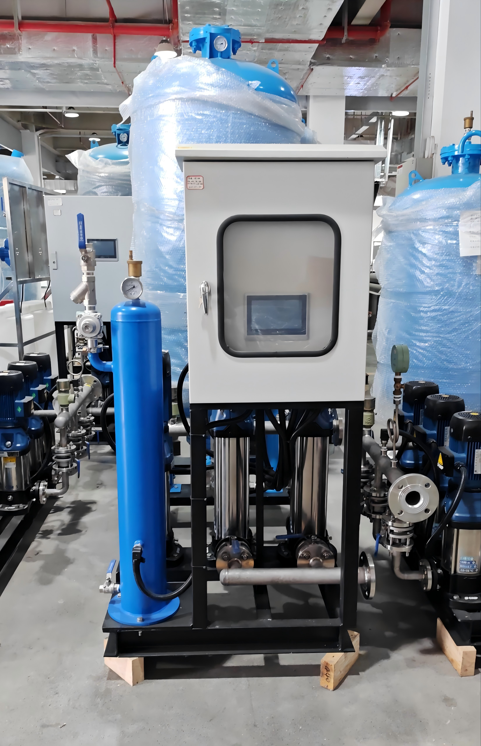
Schematic Diagram of Constant Pressure Degassing Unit

Core Advantages
Trinity Integrated Function: Integrates constant pressure regulation, automatic water supply, and vacuum degassing into one, realizing multi-functional operation with a single device, which simplifies system configuration and reduces equipment investment.
Internationally Advanced Technology: Adopts international advanced technology independently developed by our company, ensuring stable performance, high degassing efficiency, and accurate pressure control, meeting the high-standard requirements of modern water circulation systems.
Intelligent PLC Control: Equipped with a high-performance PLC control system, which realizes full automatic operation, including automatic pressure adjustment, automatic water replenishment, automatic degassing, and automatic expansion water discharge, reducing manual intervention and improving operation efficiency.
Flexible Equipment Types: Provides two types (atmospheric pressure type and forced type) to choose from, which can be flexibly matched according to the actual working conditions and requirements of the user's water system.
Customizable Configuration: Supports OEM/ODM customization according to user needs; the expansion tank material can be selected as standard carbon steel or optional stainless steel 304/316 (food-grade, high corrosion resistance) to adapt to different application scenarios.
Reliable & Durable: Adopts high-quality core components (water pumps, PLC control system, etc.) and scientific structural design, ensuring stable operation, long service life, and low failure rate, reducing maintenance costs.
Wide Applicability: Suitable for various closed water systems such as HVAC, central heating, and industrial circulation, effectively solving the problems of pressure instability, water shortage, and gas accumulation, ensuring the safe and efficient operation of the system.
Application Fields
Central Heating Systems: Applied to residential, commercial, and industrial central heating systems, used for pressure stabilization, automatic water replenishment, and degassing, ensuring uniform heating and stable system operation.
HVAC Systems: Suitable for central air conditioning water systems (chilled water, cooling water), maintaining stable system pressure, removing gas in the water, and improving the heat exchange efficiency of the air conditioning system.
Industrial Circulation Water Systems: Used in closed industrial circulation water systems of various industries, ensuring stable pressure, automatic water replenishment, and removing free gas and dissolved gas to prevent pipeline corrosion and blockage.
Other Closed Water Systems: Applicable to other closed water circulation scenarios that require constant pressure, automatic water supply, and degassing, providing comprehensive water treatment support.
Usage Methods & Safety Precautions
Usage Methods
Equipment Selection: Select the appropriate equipment type (atmospheric pressure type or forced type) and configuration according to the type of closed water system, actual working conditions, and requirements. Confirm the expansion tank material (standard carbon steel or optional stainless steel 304/316) as needed.
Installation & Commissioning: Install the equipment on a flat, firm foundation, correctly connect the inlet and outlet pipelines, power supply, and control lines. The professional technical team will commission the equipment, set relevant parameters (such as constant pressure value, water supply flow), and test the degassing, pressure stabilization, and water replenishment functions.
Automatic Operation: After commissioning, the equipment enters full automatic operation mode. The PLC control system monitors the system pressure and water level in real time, automatically adjusts the water pump operation to realize automatic water replenishment, automatically discharges expansion water when the system pressure is too high, and continuously removes free gas and dissolved gas in the system.
Daily Maintenance: Regularly inspect the operation status of water pumps, degassing tanks, and expansion tanks; check the tightness of pipelines and valves to prevent leakage. Clean the degassing tank and filter regularly to ensure degassing efficiency. Check the PLC control system regularly to ensure normal signal transmission and parameter stability.
Safety Precautions
Ensure the equipment is installed and commissioned by professional personnel to avoid equipment damage or safety hazards caused by incorrect installation and parameter setting.
During operation, do not disassemble the equipment, pipelines, or control components without permission. If any abnormality is found (such as abnormal pressure, leakage, or failure to degas), stop the machine immediately and contact professional technical personnel for maintenance.
Regularly check the pressure of the expansion tank and the operation status of the water pump to avoid equipment overload caused by excessive pressure or insufficient water supply.
When selecting the expansion tank material, choose according to the actual water quality and application scenario; for food-grade or high-corrosion-resistance requirements, select stainless steel 304/316 material.
Store and use the equipment in a well-ventilated, dry environment, away from direct sunlight, high temperature, and corrosive substances, to extend the service life of the equipment.
Operators should be familiar with the equipment operation manual before operation, and wear appropriate protective equipment when inspecting and maintaining the equipment to avoid accidental injury.
Keep the equipment out of the reach of children and unauthorized personnel to prevent misoperation and accidental injury.
FAQ
Where is the constant pressure water makeup unit applicable?
It is suitable for closed water systems such as HVAC (central air conditioning) systems, central heating systems, and industrial circulation systems. It effectively ensures stable system pressure, realizes automatic water replenishment, and removes gas in the system, ensuring the safe and stable operation of the closed water system.
What are the main components of the constant pressure water makeup unit?
The key components include an expansion tank, water pumps, a PLC control system, and valves for automatic pressure stabilization and water supply. In addition, the equipment is also equipped with a degassing tank and other supporting accessories to realize the integrated functions of degassing, constant pressure, and water replenishment.
What is the main material of the expansion tank?
The standard material of the expansion tank is carbon steel. For users with special requirements (such as food-grade standards or high corrosion resistance needs), we provide optional stainless steel 304/316 materials to meet different application scenarios.
Can we customize the equipment?
Yes, we offer OEM/ODM customization services based on your specific needs. We can customize the equipment type (atmospheric pressure type or forced type), expansion tank material, size, control parameters, and other configurations to perfectly match your actual working conditions and system requirements.
Is your company a trading company or a manufacturer?
We are a professional manufacturer with in-house production and export capabilities. Our company integrates R&D, manufacturing, and international trade, providing factory-direct prices to reduce your procurement costs. We also have a professional technical team to provide comprehensive pre-sales consultation and after-sales support.
What is the difference between atmospheric pressure type and forced type equipment?
The atmospheric pressure type is suitable for scenarios with relatively stable system pressure and small water demand fluctuations, featuring simple structure and low energy consumption. The forced type is suitable for scenarios with large system pressure fluctuations and high water demand, which can provide stronger water supply capacity and more stable pressure control to meet high-demand working conditions.
How does the equipment remove free gas and dissolved gas in the system?
The equipment is equipped with a special degassing tank, which uses vacuum degassing technology to separate free gas and dissolved gas from the water. The PLC control system monitors the gas content in the system in real time, and automatically discharges the separated gas to ensure that the system is free of gas accumulation, avoiding pipeline corrosion and heat exchange efficiency reduction caused by gas.


