


Views: 0 Author: Site Editor Publish Time: 2026-10-08 Origin: Site


Unplanned downtime in fluid processing directly impacts yield, damages downstream equipment, and spikes operational costs. When an automated filtration system fails, the root cause is rarely obvious. Operators frequently misdiagnose symptoms like erratic pressure drops, continuous backwashing, fluid starvation, or sudden leaks. This misdiagnosis leads to unnecessary component replacement or catastrophic element blow-outs. Resolving these issues requires a systematic approach rather than guesswork. This guide provides an engineering-grade framework for troubleshooting and maintaining a self-cleaning filter. By isolating mechanical, electrical, and fluid-dynamic variables, plant managers can stabilize operations. They can extend equipment lifespan and accurately calculate the Total Cost of Ownership (TCO) of their maintenance protocols. Implementing these strategies ensures that filtration systems operate at peak efficiency, preventing minor faults from escalating into major facility shutdowns.
Differential Pressure (DP) is the Primary Diagnostic: True filter health is measured by the ratio of effective filtration area to theoretical pressure loss, not just time-in-service.
Electrical vs. Mechanical Isolation: Mis-triggers (e.g., continuous backwashing) require systematic isolation, such as jumper wire testing, to differentiate between sensor failure and timer board faults.
Type-Specific Tolerances Dictate Maintenance: A hydrocyclone requires strict 3-8 psi operating parameters, while an industrial screen self-cleaning filter demands zero-gap brush alignment and industrial-grade O-ring lubrication.
Non-OEM Parts Destroy ROI: Utilizing aftermarket drive nuts or scraper blades is the leading cause of wedge wire blinding and element blow-outs, severely inflating long-term costs.
Clogging is not always a mechanical failure. It is often a shift in fluid dynamics or chemistry that the system was not specified to handle. Understanding the underlying physics of why a filter blinds is the first step in predictive system management.
Operators must distinguish between standard debris loading and high-viscosity fluid changes. Standard particulate accumulation occurs linearly. Dirt, scale, or debris is trapped by the filtration media over time. Fluid phase changes occur when temperature fluctuations or sudden pressure drops cause dissolved solids to precipitate out of the solution. This creates a sticky, tar-like substance that rapidly blinds the screen.
Scraper-type or vibration-based mechanisms are mandatory for high-viscosity or high-solid fluids. Standard flow-backwashing will fail under these conditions. The reverse fluid velocity is insufficient to shear the precipitated solids from the filtration matrix. If a system designed for low-viscosity water is suddenly subjected to high-viscosity sludge, the differential pressure will spike exponentially. This happens regardless of how often the backwash cycle is triggered.
Biological fouling presents a unique challenge. This is particularly true when managing a wastewater self-cleaning filter or a recycling-water self-cleaning filter. In these environments, bacteria, algae, and other microorganisms thrive. They secrete extracellular polymeric substances (EPS). This creates a sticky, resilient biofilm matrix across the filtration element.
Bacteria and algae create a sticky matrix that standard mechanical scraping cannot remove. The biofilm acts as an adhesive. It traps secondary particulates and creates an impenetrable layer. Because this matrix is highly pliable, mechanical scrapers often glide over it without removing it. Standard backwashing simply stretches the biofilm without breaking its bond to the screen. Resolving biological fouling requires chemical intervention. Shock chlorination or targeted biocide dosing breaks down the EPS matrix before mechanical cleaning can be effective.
Advanced filtration diagnostics rely on the dual-sensor algorithm concept. Differential pressure (DP) increases exponentially as the unblocked (effective) area decreases. A filter does not lose performance linearly. If 50% of a screen is blocked, the pressure drop might only increase slightly. Once 85% of the screen is blocked, the remaining 15% of the open area must handle the entire volumetric flow. Fluid velocity through the remaining pores skyrockets. This causes an exponential spike in DP.
This phenomenon leads to fluid starvation. The downstream pump does not receive enough liquid to maintain optimal operation. Relying solely on time-based maintenance rather than continuous DP monitoring leads to premature wear. It also causes downstream equipment cavitation. By comparing the theoretical pressure loss at a given flow rate against the actual measured DP, operators can precisely calculate the remaining effective filtration area. They can trigger cleaning cycles exactly when needed.
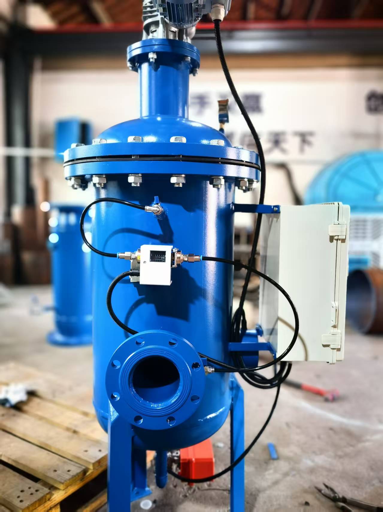
When a system experiences sudden, severe pressure differentials, leaks, or flow drops, operators need a structured diagnostic flow. A systematic approach prevents misdiagnosis. It ensures that root causes are identified before expensive components are dismantled.
Data Verification & Operator Inquiry: Cross-reference flow rates, pressure drops, and filtrate quality against baseline design parameters. A sudden DP spike might indicate that the feed pump is pushing 30% more volume than the system was designed to handle. Investigate recent upstream changes. Speak with plant operators to determine if there have been valve malfunctions or temperature shifts.
Acoustic Diagnostics: Differentiate between internal noises. Worn motor bearings produce a steady, high-pitched grind. Loose internal components create erratic rattling that changes with flow velocity. Pump cavitation sounds like gravel passing through the pipes.
Cavitation Prevention: Ensure fluid pressure remains above the liquid's vapor pressure. This is mandatory when operating an intake-water self-cleaning filter. If the filter screen becomes severely blinded, it creates a massive pressure drop. The downstream fluid pressure plummets below the vapor pressure. Bubbles form and violently collapse inside the pump impeller.
Leakage & Seal Integrity Check: Inspect gaskets, O-rings, and housings for corrosion or micro-cracks. A sudden drop in system pressure might be due to a compromised seal. Re-torque housing bolts to exact manufacturer specifications in a star pattern. This resolves micro-leaks without warping the housing flange.
Engineering-Grade System Recovery: Implement Variable Frequency Drives (VFDs) on feed pumps. This prevents sudden flow surges during startup. Initiate air-assisted backwashing. Injecting compressed air into the backwash fluid creates a highly turbulent, scouring flow. If standard backwashing fails, execute a compatible solvent or chemical soak. Isolate the filter, drain the fluid, and fill the housing with a chemical agent designed to dissolve the specific embedded contaminants.
Automated filters rely on complex on-demand cleaning systems. When a filter continuously backwashes without stopping, the issue is often a control system fault. Differentiating between a dead control panel and a faulty sensor requires systematic electrical isolation.
Before opening electrical panels, verify the physical utilities. For pneumatically actuated systems, verify the compressed air manifold pressure. If the air pressure drops below the actuator's minimum requirement, the valves will fail to open. This happens even if the electrical signal is perfect.
Confirm power to the on-demand controller and the timer board. Check the LED status indicators. A blown fuse or a tripped breaker is a common culprit. Routinely calibrate DP sensors. Sensor drift is a primary cause of premature or delayed cleaning cycles. If the high-pressure port becomes slightly clogged with silt, the sensor will read a falsely low DP. This prevents the cleaning cycle from triggering until the filter is catastrophically blinded.
To definitively determine whether a mis-trigger is caused by a faulty pressure sensor or a dead timer board, a qualified electrician should perform a jumper wire isolation test.
Step 1: Disconnect power to the control panel. Locate and remove the wire connecting the main controller to the timer board's pressure switch input.
Step 2: Install a temporary jumper wire directly across the timer board pressure switch terminals. This simulates a high differential pressure signal coming from a perfectly functioning sensor.
Step 3: Restore power to the panel. Observe the timer board. If the timer board sequentially triggers the solenoids, the board is functioning correctly. The fault lies in the controller or the DP sensor itself. If the board fails to trigger the solenoids despite the jumper wire, the timer board is dead. It requires immediate replacement.
| Symptom | Potential Component Failure | Diagnostic Action |
Continuous backwashing loop | Timer board relay stuck closed | Perform jumper wire test; check relay continuity. |
No backwash at high DP | Clogged sensor port or dead sensor | Flush sensor tubing; verify mA output signal. |
Valves click but do not open | Low pneumatic manifold pressure | Verify air compressor output is >80 psi. |
Erratic cleaning intervals | Sensor drift or loose wiring | Recalibrate DP sensor; tighten terminal blocks. |
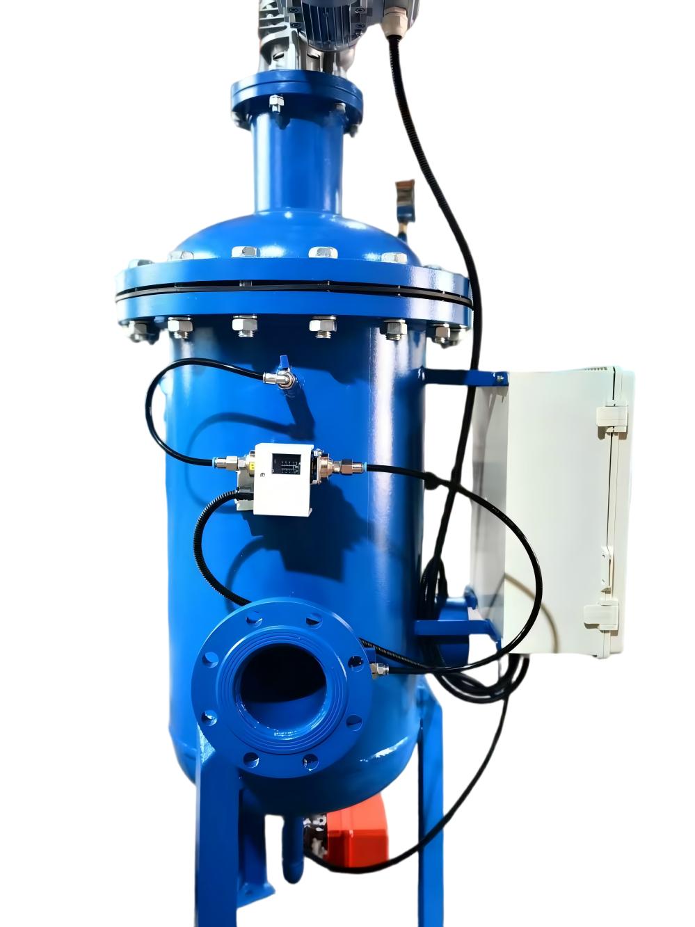
Generic maintenance advice fails in industrial filtration. Different filtration mechanisms require distinct, hard-number tolerances and specific troubleshooting steps. Applying the maintenance protocol of a sand filter to a hydrocyclone will result in rapid equipment failure.
An industrial screen filter relies on precise mechanical tolerances to function. Inspect brush mechanisms bi-annually to ensure a zero-gap between the brush bristles and the screen surface. Even a one-millimeter gap allows sticky particulates to remain on the screen. This rapidly accelerates the blinding process.
Lubrication is equally strict. Use industrial-grade silicone grease on end O-rings. Standard petroleum-based greases will degrade specific synthetic rubber compounds. This leads to chemical degradation and leakage. This is highly relevant in a desalination self-cleaning filter. High salinity and corrosive environments will quickly wash away inferior lubricants. This compromises the pressure vessel's integrity.
Disc filters operate by compressing grooved plastic discs together. During a backwash cycle, downstream pressure must hit a minimum of 30 psi. This decompresses and separates the discs effectively. If the pressure is too low, the discs remain tightly packed. The backwash water cannot flush the trapped debris. If a disc filter is continuously backwashing without stopping, immediately inspect for a torn backwash valve diaphragm.
Hydrocyclones utilize centrifugal force rather than physical barriers. The operating pressure drop must remain strictly between 3-8 psi. Operating below 3 psi destroys the centrifugal separation efficiency. Heavy solids pass through. Operating above 8 psi causes rapid internal abrasion. It sandblasts the interior walls of the cyclone. Thread grease and internal rubber wear inserts must be replaced annually.
Media filters require seasonal management and physical degradation checks. Winterization is mandatory in cold climates. The vessels must be thoroughly backwashed and drained from the lowest point during off-seasons. This prevents slime caking and internal freezing.
To determine if a raw-water self-cleaning filter needs new sand, operators should perform the tactile test. Grab a handful of the media from the bed. Efficient, high-performing sand has sharp edges that catch microscopic debris. If the sand feels rounded and smooth due to years of aggressive backwashing, the filtration efficiency has collapsed. The media must be completely replaced.
Attempting to save operational expenditure on consumable parts frequently leads to catastrophic capital expenditure losses. The precision engineering inside an automated filter means that off-brand tolerances directly compromise the cleaning mechanism.
Consider the scenario of a process-water self-cleaning filter installed in a high-volume paper mill. The filter began passing large particulates. This caused severe paper scratches and resulted in a 15% loss in highly expensive coating material. To compensate for the poor filtration, operators manually overrode the control system. They reduced the backwash cycle from once every 6 hours to once every 40 minutes.
Upon deep engineering inspection, the root cause was discovered. The facility maintenance team had installed a non-OEM drive nut and an incorrect aftermarket scraper blade material. They wanted to save a few hundred dollars. The non-OEM tolerances were slightly off. This caused the aftermarket drive nut to bind and fail along the central shaft. It prevented the cleaning disc from moving up and down the screen.
The outcome was catastrophic. Because the scraper was jammed, the wedge wire screen experienced immediate blinding. The system experienced a massive DP spike that the feed pumps continued to push against. Ultimately, this resulted in the physical rupture of the highly expensive wedge wire elements. Non-OEM tolerances directly compromise the cleaning mechanism. They make aftermarket parts a severe risk to operational ROI and plant uptime.
Even a perfectly maintained filter will fail if the purge infrastructure is flawed. Preventing back-pressure from ruining the automated cleaning cycle is a strict requirement of system design.
Drain lines must be sized correctly to handle the massive volume of water expelled during a purge cycle. Drain lines must have a minimum 4-inch diameter and a maximum length of 50 feet. If the pipe is too narrow or too long, fluid friction creates resistance. This slows the exit velocity of the purge water.
Drain lines must discharge to the atmosphere with absolutely zero back pressure. If the purge water cannot exit the housing faster than the internal pressure pushes it out, the differential pressure required to lift debris off the screen will not be achieved.
Operators must avoid installing check valves or gate valves in the purge line. These components inherently restrict flow and create internal ledges where heavy solids can accumulate. When purge flow is restricted, debris is left trapped inside the housing. This immediately triggers another DP alarm. It leads to continuous, non-stop backwashing loops that waste thousands of gallons of process water.
Reliable operation of a self-cleaning filter hinges on respecting fluid dynamics, adhering to strict DP thresholds, and utilizing OEM-spec components. When evaluating maintenance protocols or upgrading systems, prioritize equipment that offers dual-sensor DP monitoring and transparent control boards that allow for easy electrical isolation testing.
To secure your filtration infrastructure, take the following immediate actions:
Audit your current installation to verify that your drain line routing discharges to the atmosphere with zero back-pressure.
Measure your hydrocyclone and disc filter pressure parameters against the strict 3-8 psi and 30 psi baselines.
Execute the tactile test on any media filters to ensure the sand retains the sharp edges necessary for effective particle capture.
Replace all aftermarket internal drive nuts, scraper blades, and O-rings with OEM components to prevent catastrophic wedge wire blow-outs.
A: While it varies by type, a typical clean differential pressure is between 2-5 psi. Automated backwash sequences are usually triggered when the DP switch detects 6-7 psi. Spikes beyond this indicate severe blinding.
A: Continuous backwashing is usually caused by a torn backwash valve diaphragm, debris physically jamming the purge valve open, or severe back-pressure in the drain line preventing the debris from escaping.
A: Cavitation occurs when fluid pressure drops below its vapor pressure, causing bubbles to form and violently collapse. Prevent this by ensuring the feed pump provides adequate inlet pressure and that the filter screen is not severely blinded, which artificially starves the pump.
A: No. Standard petroleum-based greases can degrade specific O-ring materials and wash away in harsh environments. Always use an industrial-grade pipe silicone grease (like DC33) specified for high-corrosion or desalination applications.
A: Backwash mechanisms reverse fluid flow to dislodge particulates and are ideal for standard water applications. Scraper (mechanical) mechanisms physically wipe the screen and are required for high-viscosity fluids or liquids with very high solid concentrations where reverse flow is ineffective.
A: Perform a jumper wire test. Disconnect the sensor from the timer board and bridge the terminals with a jumper wire. If the board initiates the cleaning sequence, the board is fine and the sensor is faulty. If it does nothing, the timer board has failed.


