

Views: 0 Author: Site Editor Publish Time: 2026-05-15 Origin: Site


Commercial HVAC and hydronic heating/cooling systems routinely suffer from hidden efficiency killers. Dissolved oxygen, micro-bubbles, and volatile pressure fluctuations constantly degrade infrastructure from the inside out. Facility managers often overlook these insidious threats until catastrophic mechanical failures occur.
Traditional fragmented approaches fail to meet the precise tolerances of modern variable refrigerant flow (VRF) and advanced hydronic systems. Relying on high-level expansion tanks, fixed-speed make-up water pumps, and manual deaeration simply cannot maintain optimal fluid dynamics. This legacy hardware leads to aerobic corrosion, erratic head pressure, and severe water hammer damage across the piping network.
Consolidating these legacy components into a single automated, closed-loop unit eliminates chemical degradation and mechanical wear entirely. This technical guide evaluates the operational mechanisms, total cost of ownership (TCO) implications, and engineering requirements of deploying an Automatic degassing constant pressure water refill device. We outline how modernizing your mechanical room protects high-value downstream assets while recovering critical operational space.
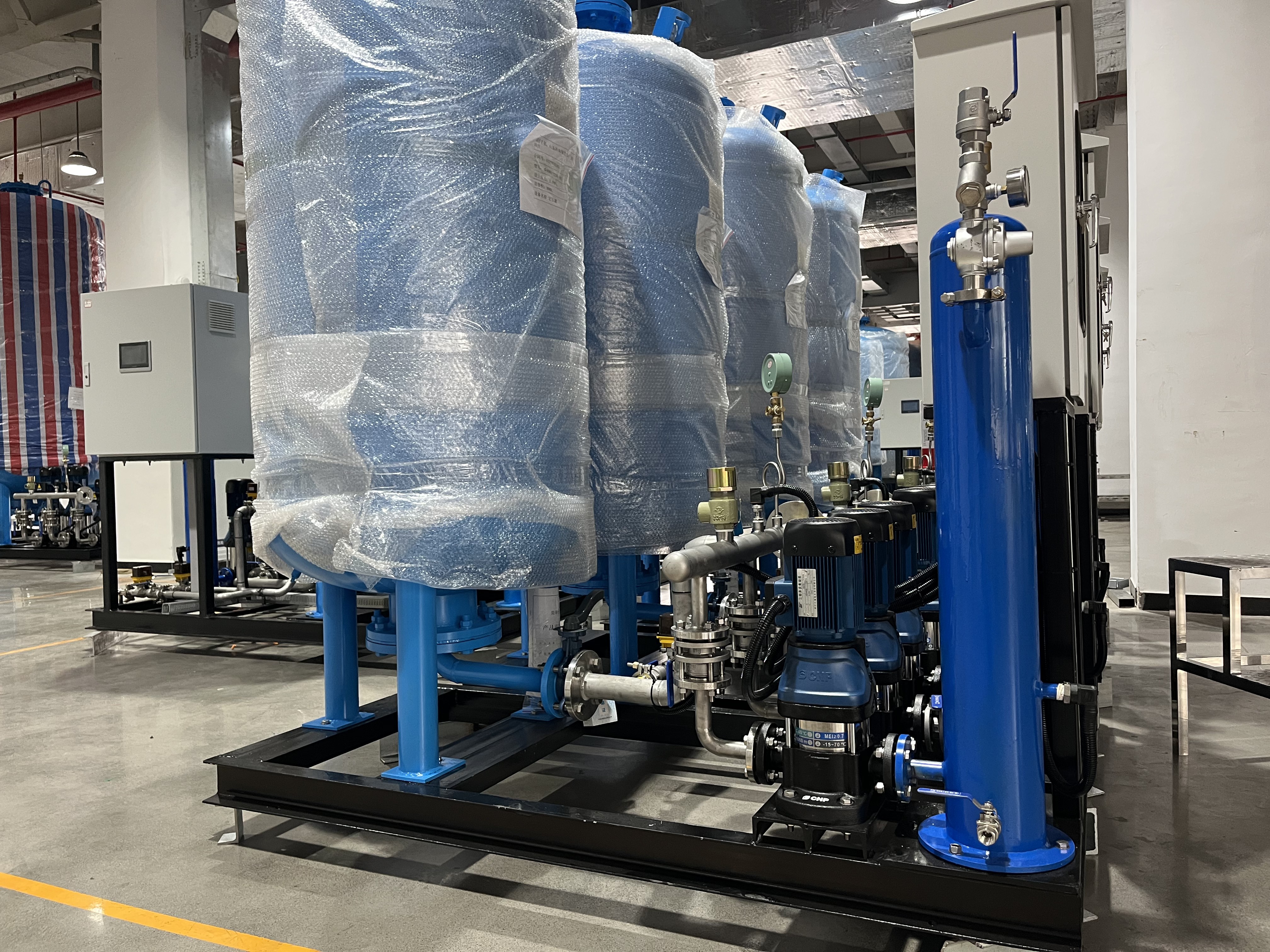
4-in-1 Consolidation: Replaces massive traditional expansion tanks and separate make-up pumps with a unified system managing pressurization, expansion, make-up water, and vacuum degassing.
Corrosion & Acid Eradication: Operates without heat, utilizing vacuum physics to strip >99% of dissolved oxygen and free gases, preventing moisture from reacting with modern refrigerants and synthetic lubricants to form damaging acids.
Granular Pressure Control: Shifts from the volatile 40-60 PSI swings of traditional fixed-speed pumps to highly sensitive variable frequency drive (VFD) responses triggered by pressure drops as low as 5 PSI.
Measurable ROI & Asset Value: High initial capital expenditure (CapEx) is offset by a 40–60% reduction in equipment footprint, elimination of chemical oxygen scavengers, lowered electrical consumption, and enhanced overall commercial facility valuation.
Dissolved oxygen remains the most destructive element introduced via raw make-up water. Henry's Law dictates that cold municipal water holds high concentrations of dissolved gases. When this fresh water enters a warm hydronic loop, its gas solubility drops, releasing free oxygen directly into the fluid stream. This oxygen reacts aggressively with iron and steel piping. The resulting iron oxide creates abrasive rust flakes that circulate continuously. These heavy particulates settle in low-flow areas, creating thick sludge that chokes control valves and fouls delicate heat exchanger plates.
Modern HVAC systems utilize synthetic lubricants, such as polyolester (POE) and polyvinyl ether (PVE) oils. These advanced synthetic oils are highly hygroscopic. They eagerly absorb stray moisture from the fluid network. When untreated moisture and oxygen interact with modern refrigerants under high compressor heat, they trigger a rapid chemical breakdown. This hydrolysis generates aggressive acidic compounds. Hydrofluoric and hydrochloric acids accelerate internal rusting, eat through the copper enamel on compressor windings, and destroy lubricant viscosity. Over time, this chemical cascade directly causes premature mechanical seizure.
Entrained air and micro-bubbles act as powerful thermal insulators within the fluid stream. Air possesses a thermal conductivity rating drastically lower than water. When micro-bubbles coat the internal metallic surfaces of heat exchangers, they form a barrier that severely reduces heat transfer efficiency. A hydronic system struggling to transfer heat forces chillers and boilers to run extended cycles. This artificial load spikes energy consumption and increases mechanical wear on the primary plant.
Trapped gases also trigger severe pump cavitation. This phenomenon destroys pump internals rapidly. As micro-bubbles pass into the low-pressure eye of a pump impeller, they rapidly expand. When the impeller pushes these bubbles into the high-pressure discharge zone, they violently collapse. This implosion generates localized microscopic shockwaves exceeding 10,000 PSI. The shockwaves pit and erode bronze or cast iron impellers over time. Cavitation sounds like marbles rattling inside the pump casing, serving as a clear audible warning of active mechanical destruction.
Head pressure suffers heavily from trapped air and erratic fluid dynamics. Unpredictable pressure drops can cause evaporator coils to freeze completely. Conversely, trapped non-condensable gases occupy physical volume inside the condenser. This forces the compressor to work against artificially high head pressure. The resulting excessive motor loads and high amp draws trigger thermal overloads, destroying costly commercial compressors.
Traditional water make-up pumps rely on blunt-force mechanics. They typically operate at maximum RPM, but only activate after detecting a severe system pressure drop. This forces the piping network to endure constant, violent swings from low-pressure lulls to sudden high-pressure surges. Modern HVAC infrastructure requires strict, continuous pressure stability to protect sensitive electronic expansion valves and variable speed components.
These hydraulic shocks cause long-term physical fatigue. The kinetic energy of rapidly moving water slamming into closed valves degrades pipe fittings and joints. Over decades, this relentless physical stress leads to hairline fractures, blown gaskets, and catastrophic pipe bursts.
Multi-story buildings present severe elevation challenges. Gravity induces continuous static head pressure decay at higher floors. A standard rule dictates you lose about 1 PSI for every 2.31 feet of vertical elevation. A traditional system often leaves top-floor terminal units starved for adequate flow. Dynamic, constant pressure compensation provides the required upward force to overcome static head pressure. Advanced systems continuously push water upward, ensuring uniform flow rates and thermal comfort across every floor of a high-rise facility.
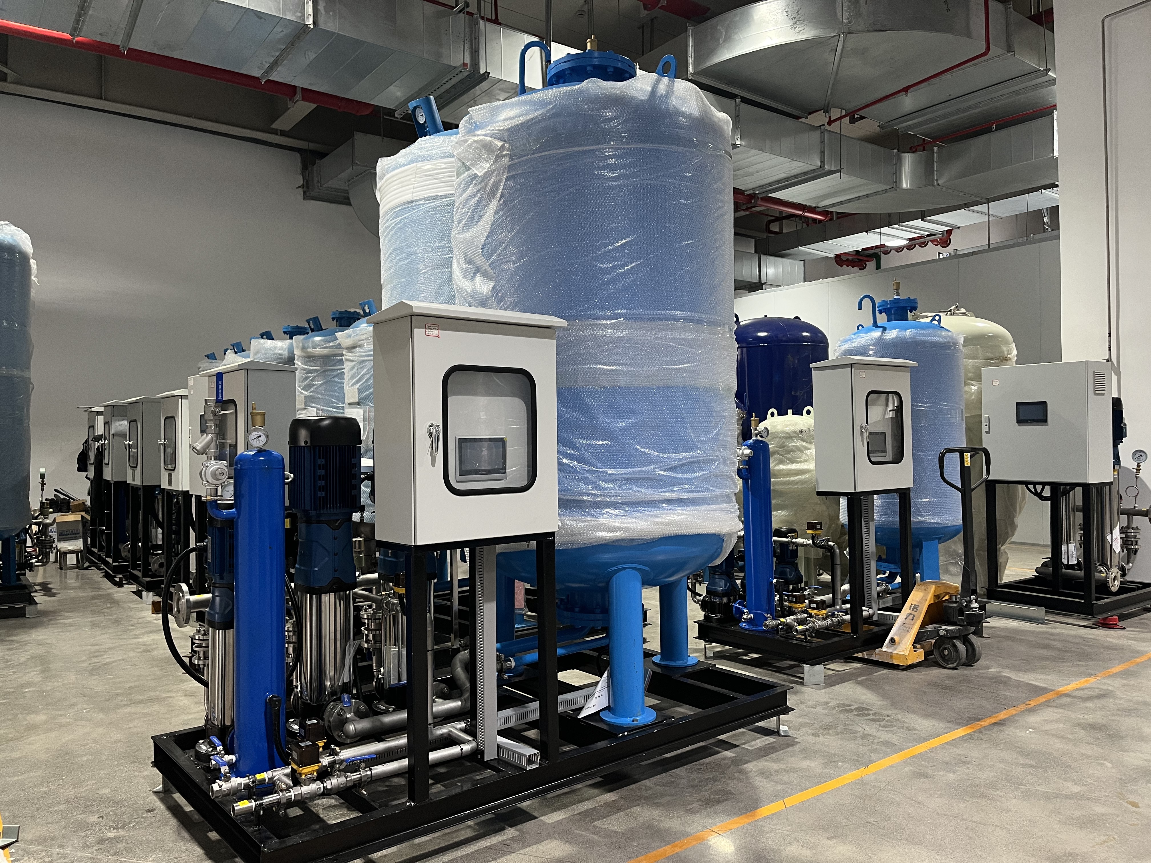
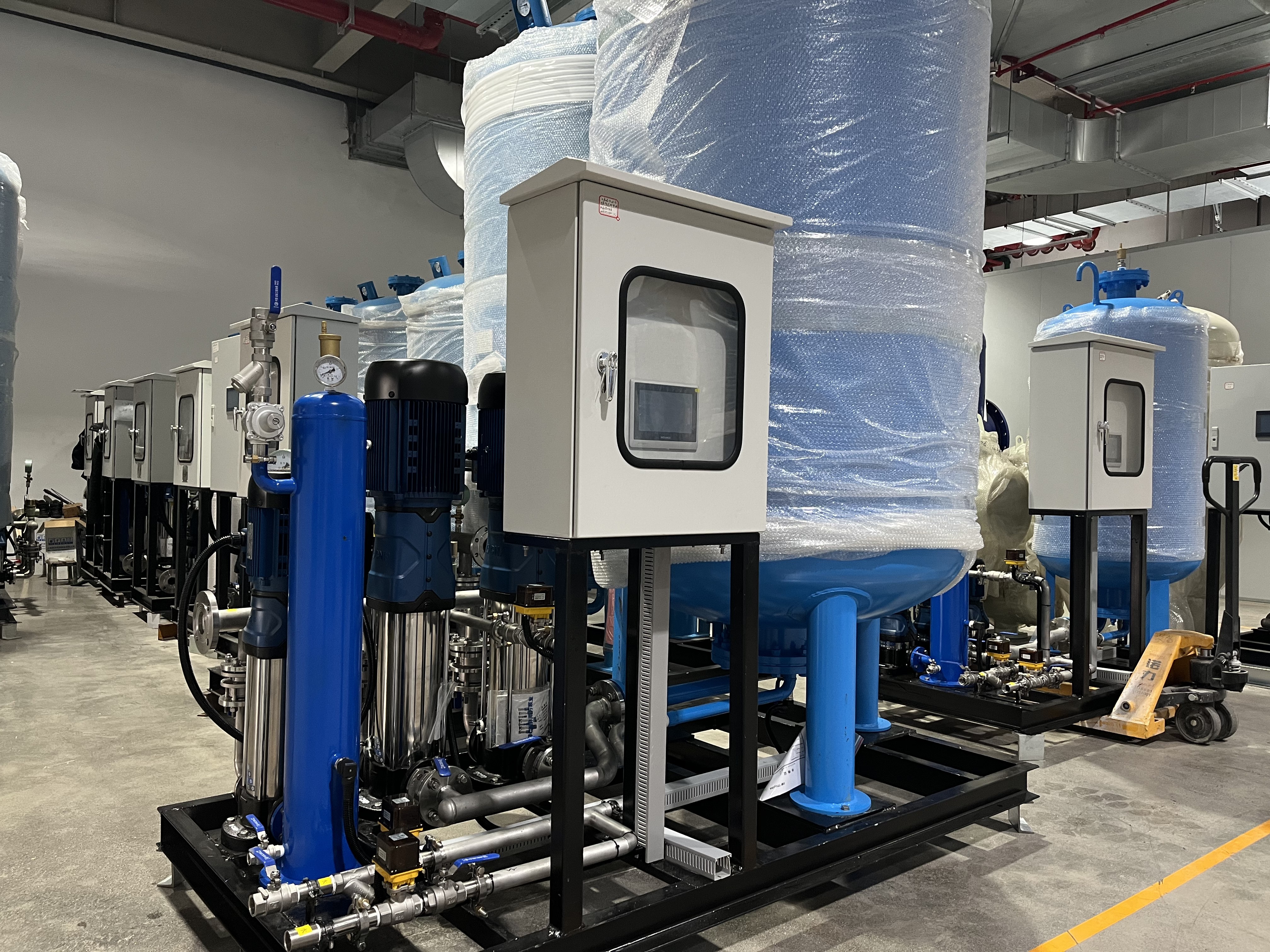
Modern facility management demands strict spatial and operational efficiency. The 4-in-1 architecture provides exact operational synergy across four core functions. It handles dynamic pressurization, absorbs thermal expansion, automates water make-up, and performs continuous vacuum degassing. This unified approach eliminates the fragmented failure points inherent in older mechanical room designs.
This architecture renders standalone high-level water towers and fixed-speed jockey pumps obsolete. It also removes the need for bulky diaphragm expansion tanks. An Integrated expansion degassing unit uses a highly efficient atmospheric buffer tank. It dynamically absorbs thermal expansion through automated proportional valves and variable pump control. As water heats up and expands, the controller diverts excess volume into the buffer. As it cools and shrinks, the pump pushes that exact volume back into the loop. By consolidating these functions, building owners recover premium mechanical room space for other structural needs.
Vacuum degassing relies on fundamental physics rather than brute-force thermal heating. Lowering the internal pressure within the degassing chamber artificially lowers the boiling point of the water. This rapid pressure drop forces dissolved gases and micro-bubbles to separate from the liquid phase. The system then vents these extracted gases to the atmosphere automatically. This process requires very little electrical energy compared to traditional steam or thermal deaerators.
This methodology achieves remarkable baseline performance metrics. Quality systems guarantee a deaeration efficiency exceeding 99%. To achieve this, the internal vacuum pump pulls the chamber down to specific negative pressure thresholds. The water sprays through a specialized nozzle into the vacuum, maximizing surface area and forcing rapid outgassing. Technicians utilize decay testing during commissioning to verify integrity. By isolating the system and monitoring the vacuum gauge, they differentiate between internal outgassing (a slow pressure rise) and physical system leaks (rapid, sharp pressure spikes).
Precision control relies entirely on industrial-grade piezoresistive differential pressure transmitters. These sensors continuously monitor the system loop for microscopic pressure variations. To maintain accuracy, installers must shield these sensors from severe mechanical room conditions. Electrical noise from high-voltage switchgear, high ambient humidity, and extreme temperature swings can cause sensor drift. This drift provides inaccurate system feedback to the master controller.
An Intelligent pressurization degasser acts as the central nervous system. It interprets data from the shielded sensors and adjusts the Variable Frequency Drive (VFD) via strict Proportional-Integral-Derivative (PID) logic. Instead of basic on/off toggling, the PID logic allows the pump motor to smoothly adjust its hertz frequency. The pump gently "sips" water for minor thermal adjustments or "gulps" water during major system volume losses. This continuous modulation guarantees absolute pressure stability across the entire HVAC loop.
Traditional setups suffer from wide operational deadbands. They wait passively for system pressure to plummet to a specific cut-in threshold, often around 40 PSI. Once triggered, the fixed-speed pump surges fluid into the pipes until hitting a 60 PSI cut-out limit. This volatile 20 PSI deadband causes erratic fluid velocities. It disrupts the balancing valves and causes inconsistent heat transfer at the terminal units.
An integrated system utilizes high-resolution VFDs that react to minute pressure drops. They sense and respond to variations as low as 2 to 5 PSI. This immediate, granular response maintains a flat, continuous pressure curve. This strict stability protects structural pipe integrity, minimizes hydraulic shock, and eliminates disruptive flow variations in critical hydronic zones.
Gravity-fed traditional systems demand heavy, reinforced roof structures to support massive water reserves. Lower-level mechanical rooms must allocate significant square footage for sprawling ASME diaphragm pressure vessels. A 10,000-gallon hydronic system might require a 1,000-gallon expansion tank. These spatial requirements complicate architectural design and increase structural construction costs.
A Compact degassing make-up system changes the architectural math entirely. It utilizes an unpressurized atmospheric buffer tank. Because the tank is unpressurized, the system can utilize nearly 100% of the internal volume, whereas pressurized diaphragm tanks only yield about 40% acceptance volume. This reduces structural payload and spatial requirements by up to 60%. Installers can easily maneuver these compact skids through standard commercial doorways without requiring building alterations or heavy structural rigging.
Legacy systems rely heavily on analogue pressure gauges and isolated electrical relays. Facility teams must physically walk the mechanical room to inspect these gauges to verify operational status. This lack of telemetry prevents proactive maintenance. It delays critical failure notifications until after flooding or equipment damage occurs.
A Digital constant pressure skid utilizes open industrial protocols like Modbus RTU, BACnet MS/TP, and standard 4-20mA signaling. This allows seamless integration with Building Automation Systems (BAS). Operators map specific data points to the BAS interface. They monitor system pressure, VFD frequency, daily make-up water volume, and specific alarm states remotely. This IoT connectivity mitigates catastrophic failure risks in mission-critical environments, including high-density data centers and pharmaceutical cold storage facilities.
| Evaluation Metric | Traditional Pump & Tank System | Integrated VFD Degassing Skid |
Pressure Fluctuation | Wide deadbands (40 to 60 PSI surges) | Maintains flat curve (reacts to 5 PSI drops) |
Space & Payload | Massive mechanical room or reinforced roof needed | Up to 60% smaller footprint, easy to retrofit |
Deaeration Method | Manual bleed valves or toxic chemical scavengers | Automated vacuum physics (>99% efficiency) |
BAS Telemetry | Analogue gauges requiring manual daily checks | Modbus / BACnet / Remote IoT integration |
Energy Consumption | Pump runs at 100% maximum RPM only | VFD scales power draw precisely to system demand |
Procuring an Automatic make-up degassing unit requires a higher initial capital expenditure (CapEx) compared to a basic pump-and-tank setup. An integrated skid might cost $15,000 upfront, whereas a legacy pump and diaphragm tank costs $7,000. However, evaluating the total cost of ownership (TCO) over a 10-year operational model reveals significant financial advantages.
The operational savings (OpEx) accrue rapidly. Electrical consumption drops drastically because VFD pumps run only precisely as needed at lower hertz frequencies. Facilities entirely eliminate the recurring annual costs of purchasing and dosing toxic chemical oxygen scavengers. Furthermore, maintenance teams no longer waste costly labor hours manually purging air from high-point bleed valves across the building. These compounded savings typically offset the higher CapEx within the first three to four years of continuous operation.
| Cost Category (Estimated 10-Year Span) | Legacy Approach | Integrated Degassing Unit |
Initial Equipment & Installation (CapEx) | $7,000 | $15,000 |
Chemical Oxygen Scavengers (OpEx) | $25,000 ($2.5k/yr) | $0 (Eliminated via vacuum extraction) |
Manual Bleeding Labor (OpEx) | $15,000 ($1.5k/yr) | $2,000 ($200/yr for routine sensor checks) |
10-Year Total Cost of Ownership | $47,000 | $17,000 |
Corrosive oxygen and abrasive particulate matter silently destroy high-value downstream assets. By keeping hydronic loops >99% free of these threats, facilities defer massive capital replacement costs. Chillers, commercial boilers, and primary heat exchangers enjoy significantly extended lifecycles. Preventing a single premature chiller tube bundle replacement easily justifies the lifetime cost of a modern pressurization skid.
Deploying advanced, energy-efficient mechanical infrastructure directly impacts commercial property valuation. These systems support points for LEED v4.1 O+M certification regarding water efficiency and energy performance. They also align with corporate ESG (Environmental, Social, and Governance) compliance mandates. Prospective buyers and premium tenants place high financial value on modernized, low-risk HVAC infrastructure that guarantees stable, predictable long-term operating costs.
Air-locked cooling loops and burst pipes cause catastrophic facility downtime. In environments like hospitals, laboratories, or server farms, cooling interruptions result in severe financial penalties and life-safety liabilities. Unstable pressurization acts as a primary trigger for these sudden mechanical failures.
Implementing continuous, flat-curve pressurization serves as a mandatory mechanical insurance policy. It eliminates the hydraulic shocks that blow out Victaulic couplings and the cavitation that destroys secondary pumps. By paying a slight premium for integrated hardware, facility managers purchase guaranteed mechanical uptime and absolute operational peace of mind.
Before installing any modern pressurization equipment, engineering teams must execute a comprehensive vulnerability audit on the existing piping. You must perform non-destructive testing (NDT), such as ultrasonic thickness gauging, to check pipe wall integrity. Older, heavily calcified systems often hide severe structural weaknesses behind years of internal scale buildup.
Traditional systems allow pipes to rest during low-pressure lulls. An integrated unit subjects the entire network to continuous, unwavering static pressure. If older joints or corroded threaded fittings cannot handle sustained pressure, they will rupture. Identifying and replacing these weak points during the audit prevents catastrophic flooding immediately following installation. Engineers typically mandate a hydrostatic pressure test at 1.5 times the intended working pressure for four hours to verify structural readiness.
Proper sizing prevents short-cycling and ensures optimal vacuum degassing performance. Engineers must match the device to the specific building profile using exact formulas. You must calculate the exact static head pressure based on building elevation. You must determine the total water volume of the hydronic loop. Finally, you calculate the anticipated thermal expansion capacity by evaluating the minimum and maximum fluid operating temperatures.
Initial system commissioning requires meticulous attention to physical flow dynamics. Installers must remove any physical throttling restrictions from the make-up water lines. Leaving narrow gauge hoses, partially closed gate valves, or standard Schrader valves in place severely chokes flow velocity. Removing these bottlenecks ensures the internal vacuum chamber receives adequate fluid volume to perform efficient micron-level outgassing.
Facility managers must understand that a constant pressure system cannot perform miracles against physical supply limitations. If the primary municipal make-up water source has a fundamentally low yield or poor incoming pressure, the system cannot spontaneously generate water volume. The VFD pump can only boost and regulate the raw water that the municipal supply actually delivers. If supply is inadequate, the facility must install an intermediate break tank.
While the unit permanently halts future aerobic corrosion, it cannot clear existing physical blockages. It will not dissolve severe mineral scale build-up or solid rust clogs already choking terminal unit coils. Highly degraded piping systems require a comprehensive chemical flush. Contractors use an organic acid blend, followed by a passivation agent and mechanical filtration, prior to installing the new degassing unit.
Take the following technical actions to initiate your mechanical room upgrade effectively:
Schedule an engineering audit to document your exact make-up water consumption, daily pressure fluctuations, and peak thermal expansion volumes.
Test your existing closed-loop water samples for dissolved oxygen levels, suspended solids, and acidic pH degradation.
Conduct a hydrostatic pressure test and ultrasonic thickness gauge assessment on legacy piping to verify structural readiness for continuous pressurization.
Request total cost of ownership (TCO) models comparing your current annual chemical scavenger costs against the operational profile of a VFD degassing skid.
Specify open-protocol BAS connectivity via Modbus or BACnet during the procurement phase to guarantee seamless remote monitoring and alarm integration.
A: Thermal degassing uses high heat to boil off dissolved gases, consuming massive amounts of energy. Vacuum degassing lowers internal chamber pressure to extract gases at room temperature. This makes vacuum technology highly energy-efficient and strictly compliant with tight micron-level evacuation standards required for modern chilled and ambient HVAC loops.
A: Yes. The integrated system absorbs thermal expansion dynamically using a much smaller, intelligent buffer tank combined with automated proportional release valves. This modern architecture completely eliminates the spatial requirement for massive, fixed-volume traditional diaphragm tanks.
A: The master controller continuously tracks VFD activity and make-up water intake volumes. If the unit detects the pump running continuously or rapid cycling beyond calculated thermal expansion parameters, it differentiates this sharp intake from the slow decay of standard outgassing. It then triggers a physical leak alarm via the BAS.
A: No. It permanently halts future aerobic corrosion by removing oxygen and moisture from the make-up water. However, it cannot dissolve existing calcification or rust blockages. Heavily degraded systems must undergo a chemical acid flush and structural pressure testing prior to installation.
A: The system requires minimal but precise maintenance. Technicians must perform routine checks of the VFD drive electrical contacts. They should also inspect the piezoresistive differential pressure sensors for environmental drift, and conduct annual testing of the vacuum pump seals and automated air-vent valves.


