


Views: 0 Author: Site Editor Publish Time: 2026-09-01 Origin: Site


Industrial water treatment systems require rigorous pretreatment to prevent catastrophic fouling of downstream equipment. Reverse osmosis (RO) membranes and high-pressure boilers remain highly vulnerable to particulate contamination. Feed water containing high Total Suspended Solids (TSS), elevated turbidity, and a Silt Density Index (SDI) above 3.0 will rapidly degrade these sensitive purification systems. This degradation leads to premature membrane replacement, severe thermal efficiency loss, and voided manufacturer warranties. Plant operators must address these parameters before water reaches the primary purification stages.
A properly sized Multimedia Filter acts as the primary defense line against these destructive particulates. Facility engineers rely on this technology to intercept suspended solids before they reach critical downstream processes. By utilizing multiple layers of stratified media, these systems offer superior dirt-holding capacity compared to traditional single-media alternatives. This guide breaks down the engineering specifications, operational cycles, and sizing criteria required to evaluate and implement these filtration systems effectively.
RO Membrane Protection: The permissible SDI for RO feed water is determined based on the water source and the membrane manufacturer's design specifications; for instance, the DuPont FilmTec technical manual lists recommended SDI values—such as <1, <3, and <5—depending on the specific water source.
Filtration Precision: Standard MMFs capture particulates down to 15–20 microns (or 5–10 microns with coagulants) utilizing the entire bed depth. For context, a human hair is approximately 50 microns wide.
Operational Triggers: Backwashing must be initiated when the differential pressure (Delta-P) reaches 10 psi above the clean state, or when effluent turbidity increases by 10%.
Flow Rate Constraints: Optimal service flow rates range from 3–7 gpm/sq ft for general industrial pretreatment, while backwash rates require 12–15 gpm/sq ft to achieve necessary bed fluidization. Specifically, service flow rates are adjusted according to water sources: 3–5 gpm/sq ft for surface water with high organic loads, 5–10 gpm/sq ft for low-turbidity well / beach-well water, and 15–20 gpm/sq ft for circulating pool water.
Engineers differentiate multimedia filters from single-media sand filters and dual-media configurations based on bed composition. Single-media filters typically utilize only silica sand, which traps debris primarily at the surface layer. This surface loading causes rapid pressure drops and shortens filtration cycles, forcing operators to backwash the system frequently. In contrast, a multimedia setup utilizes three or more layers of media. These layers feature varying densities and particle sizes. This specific configuration achieves true depth filtration, offering significantly higher dirt-holding capacity and longer service runs between backwash cycles.
The transition from single-media to multimedia represents a fundamental shift in fluid dynamics. In a standard sand filter, the finest particles migrate to the top during backwashing, meaning the water encounters the tightest filtration layer first. This design inherently limits the filter's capacity. Multimedia systems reverse this logic. By using lighter, coarser media at the top and heavier, finer media at the bottom, the water passes through progressively tighter layers. This allows the entire depth of the bed to participate in the filtration process.
Particulate removal within the filter bed relies on three distinct physical mechanisms working simultaneously:
Straining: This involves the physical blocking of debris. Particles larger than the pore spaces between media granules cannot pass through the bed. The top layer of anthracite performs the bulk of the macro-straining.
Interception and Impingement: Smaller particles adhere to media surfaces. Fluid dynamics and inertia force these micro-particles to collide with and stick to the rough edges of the filtration media. Van der Waals forces play a minor but measurable role in keeping these particles attached.
Sedimentation: Micro-particles settle within low-velocity micro-zones deep inside the filter bed. Gravity pulls these dense particles out of the water stream during downward flow, effectively trapping them in the interstitial spaces of the garnet layer.
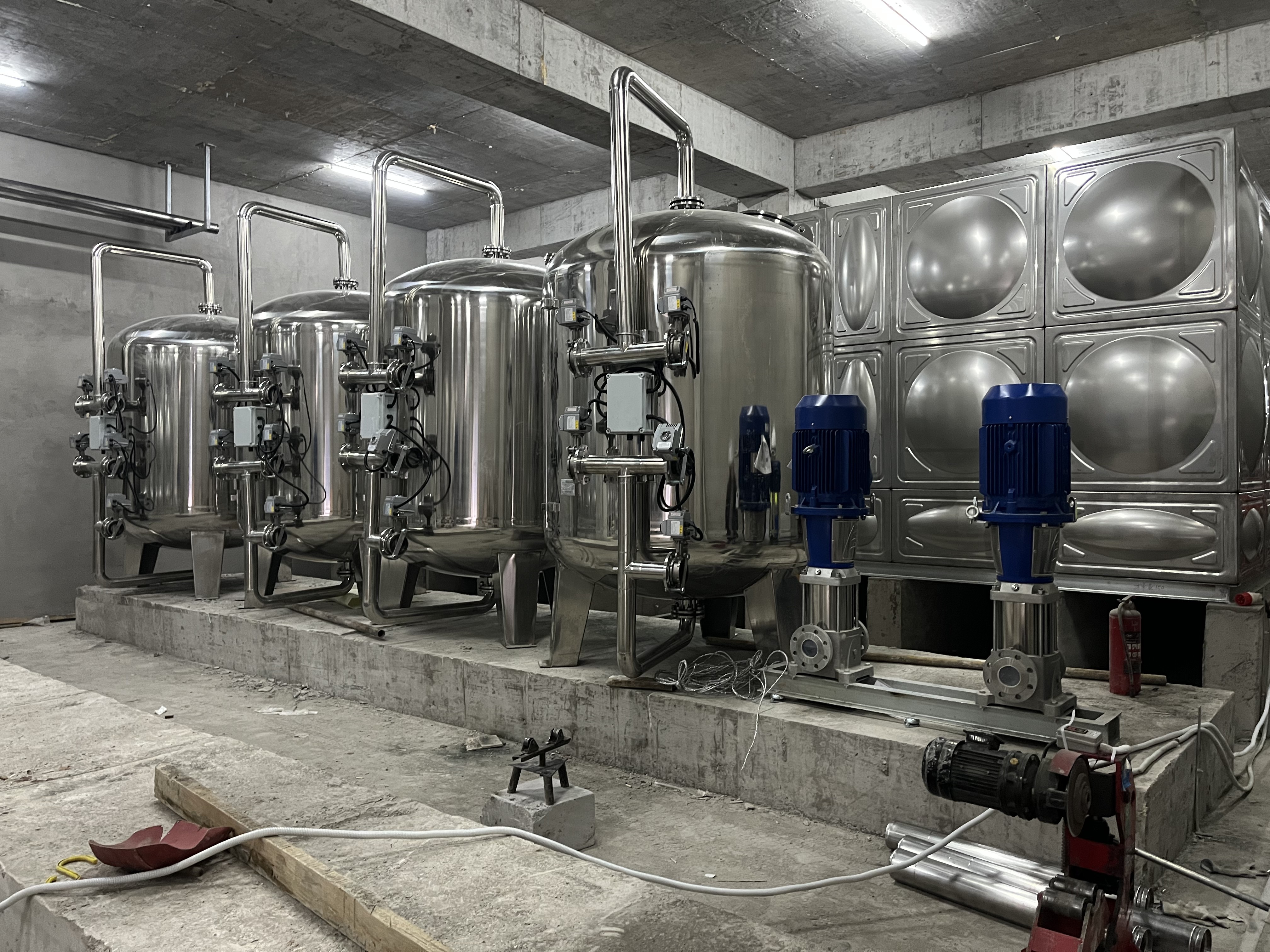
Evaluating this technology requires a clear understanding of its operational boundaries. The primary advantage is eco-friendly operation. The system requires no chemicals under normal conditions, though some facilities inject polymer coagulants to enhance fine particle capture. It remains highly effective at removing dirt, sand, rust, and suspended solids. Plant managers appreciate the low operating expenses associated with media filtration compared to disposable cartridge filters.
However, limitations exist. The media cannot remove dissolved organics, heavy metals, or bacteria. The equipment also requires a larger physical footprint compared to cartridge filters. Furthermore, the necessary backwash cycles generate wastewater that facilities must manage. If a plant faces strict discharge limits, the backwash water may require secondary treatment in a clarifier or settling tank before release.
Beyond standard RO pretreatment, these systems serve multiple industrial sectors. Stormwater management facilities use them to remove urban runoff suspended solids and phosphorus before discharging into sensitive waterways. The oil and gas industry deploys them for produced water treatment, effectively stripping fine solids from refinery wastewater to protect injection wells from plugging. Municipalities utilize them for lagoon and wastewater polishing to meet strict environmental discharge standards. Food and beverage plants rely on them to ensure ingredient water meets clarity specifications before entering the carbon filtration stage.
The internal architecture relies on an inverse relationship between particle size and density. The bed depth to particle size ratio (L/D ratio) typically measures 800–1000:1. This precise layering ensures optimal filtration efficiency and prevents the layers from mixing during the fluidization phase of the backwash cycle.
Anthracite (Top): Features a large particle size (0.85 - 1.2 mm) and low density (Specific Gravity ~1.6). It captures coarse debris like leaves, organic matter, and large sediment. This layer typically constitutes 40-50% of the total bed depth.
Silica Sand (Middle): Possesses medium size (0.45 - 0.55 mm) and density (Specific Gravity ~2.6). It captures silt and fine sediment, significantly improving water clarity. This layer makes up about 30-40% of the bed.
Garnet (Bottom): Features a small particle size (0.15 - 0.30 mm) and high density (Specific Gravity ~4.0). It captures microscopic impurities down to 10-20 microns. This highly dense layer sits just above the support gravel.
Gravel (Support Base): This layer does not filter water. It ensures even water distribution and protects the delicate underdrain laterals from damage. It usually consists of graded rock ranging from 1/8 inch to 1.5 inches in diameter.
Total Cost of Ownership (TCO) heavily depends on vessel material selection. Engineers must match the tank material to the specific feed water chemistry and operating environment. Selecting the wrong material leads to premature corrosion, structural failure, and costly downtime.
| Material Type | Key Characteristics | Best Application Scenarios |
Fiberglass Reinforced Plastic (FRP) | Lightweight (1/4 weight of steel), corrosion-resistant, non-conductive, NSF/ANSI 61 certified. Cannot withstand vacuum conditions. | Seawater desalination, brackish water, commercial systems, light industrial use. |
Epoxy-Coated Carbon Steel | High temperature and pressure tolerance, vacuum-resistant, ASME-certified. Requires periodic coating inspections. | Heavy industrial plants, high-pressure municipal systems, large-scale mining operations. |
Stainless Steel (304/316L) | Maximum durability, highly sanitary, chemical resistant, customizable with manways. High initial capital cost. | Pharmaceutical, food and beverage, extreme environments, semiconductor manufacturing. |
Internal distribution systems require robust construction. Manufacturers typically construct these internals from Schedule 80 PVC, CPVC, or stainless steel wedge wire. Durable internals prevent catastrophic failure during high-pressure backwash cycles. The hub-and-lateral or header-lateral designs must distribute water perfectly evenly across the entire cross-sectional area of the vessel to prevent channeling and ensure uniform bed expansion.
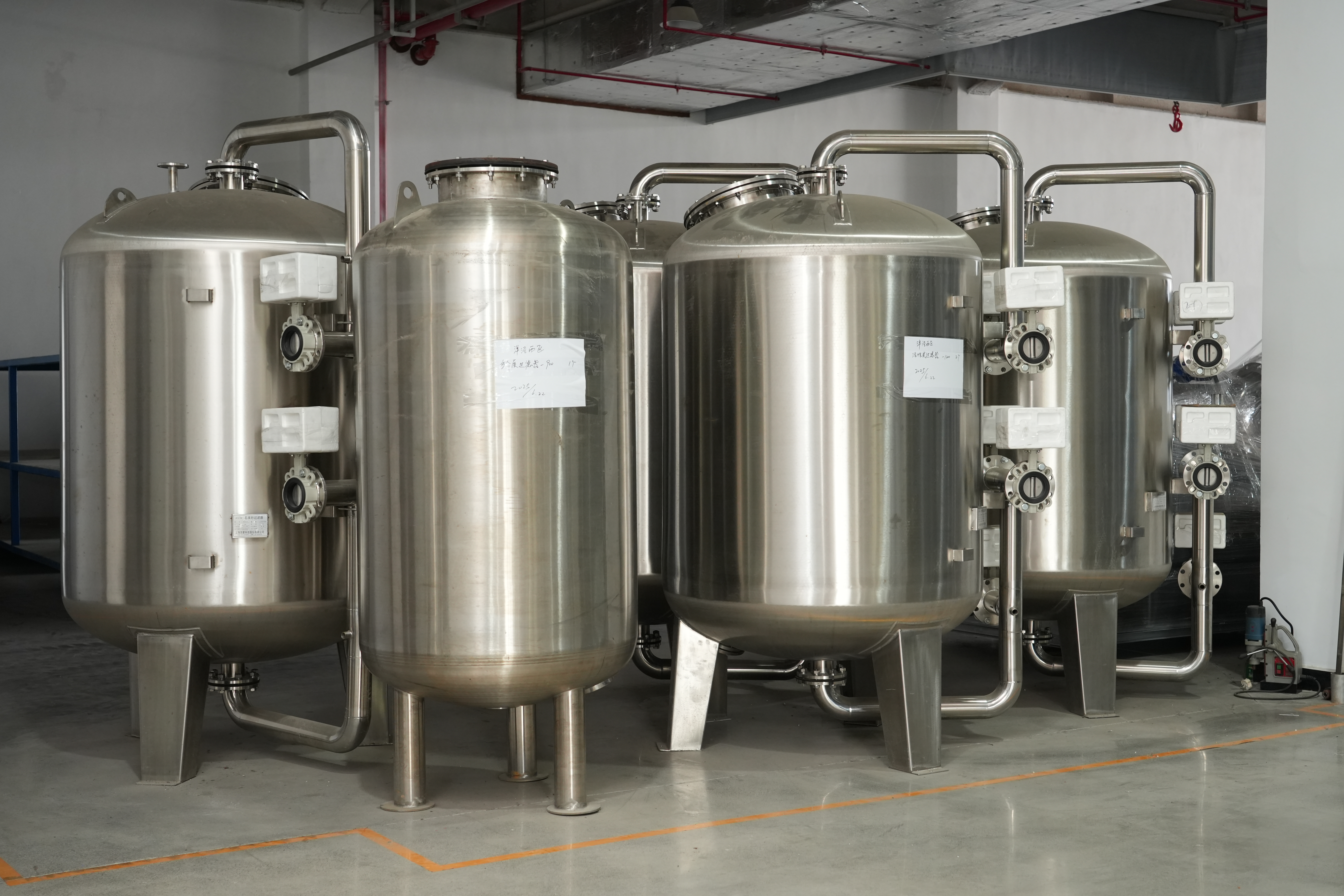
The service cycle utilizes downward flow mechanics. Raw water enters the top distributor, hits a baffle to prevent bed disturbance, and percolates through the stratified media. Recommended service flow rates depend entirely on the source water quality and the desired effluent clarity:
Surface Water: 3–5 gpm/sq ft. High organic loads require slower velocities to prevent pushing particulates through the bed.
Well / Beach-Well Water: 5–10 gpm/sq ft. Lower suspended solids allow for higher throughput.
Pool Water: 15–20 gpm/sq ft. Continuous recirculation allows for high-velocity filtration where single-pass perfection is not required.
Operators trigger the backwash cycle when the differential pressure (Delta-P) reaches 10 psi above the clean state. This phase reverses the flow upward. It requires 12–15 gpm/sq ft to expand and fluidize the bed by 40–50%. This expansion scours the media, releasing trapped particulates into the drain. Seasonal water temperature critically impacts this phase. Cold water is more viscous. It requires lower flow rates to prevent expensive media loss from the top of the vessel. Conversely, warm summer water requires higher flow rates to achieve the same 40% bed expansion.
The settling cycle remains a critical yet often overlooked phase. This 15-20 minute static period halts all water flow. It allows the fluidized media to re-stratify naturally by density. The heavy garnet falls first, followed by the sand, and finally the lighter anthracite. Proper settling prevents media mixing, maintains the filtration gradient, and saves substantial amounts of water by preventing the need for repeated backwashes.
The ripening phase resumes downward flow for 1-2 minutes. Instead of sending this water downstream, the system discharges it to the drain. This action compacts the bed tightly. It flushes out any residual particulates dislodged during backwashing, ensuring only pristine water reaches downstream processes. Skipping this step guarantees a spike in turbidity and SDI in the downstream equipment immediately following a backwash
Heavy particulate loads often require an Advanced Multimedia Filter design utilizing air scour technology. Injecting air before or during the water backwash aggressively agitates the media. Standard parameters dictate an air intensity of approximately 15 m³/(m²·h) at ≤ 0.15 MPa. The subsequent water wash intensity requires roughly 40 m³/(m²·h). This combined approach breaks up stubborn biological growth and compacted solids that water alone cannot dislodge.
Implementing an air scour system requires specific internal modifications. The underdrain must feature specialized nozzles capable of distributing air evenly without structural failure. If the air distribution is uneven, violent localized boiling occurs within the bed, which can permanently mix the media layers and destroy the filter's efficiency.
Improper operation leads to severe mechanical failures. Facility operators must monitor for two primary issues that compromise water quality:
Mud Ball Formation: These solid masses form due to insufficient backwash flow, uneven air distribution, or oil accumulation. Broken underdrains also contribute to this issue. Mud balls reduce the active filtration area, increase pressure drops, and eventually sink into the gravel layer, requiring a complete media dig-out.
Channeling: Water always seeks the path of least resistance. If the bed compacts unevenly or if mud balls form, water bypasses the media through narrow channels. This leads to immediate breakthrough of contaminants and total system failure, sending highly turbid water directly into sensitive RO membranes.
Media Washout: Occurs when backwash flow rates exceed the terminal settling velocity of the anthracite layer. Operators must verify flow restrictors and adjust backwash valves seasonally to account for water viscosity changes.
Implementing a Multimedia Filter for pure water preparation serves as mandatory pretreatment for RO, Electrodeionization (EDI), and ultrafiltration units. RO membranes feature microscopic pores that foul instantly upon contact with heavy silt. Failing to maintain an SDI below 3.0 will definitively void RO membrane warranties and cause irreversible damage. The financial impact of replacing a primary RO membrane array far exceeds the capital cost of a properly engineered filtration system.
Engineers often sequence different media vessels to address complex water chemistry. Green Sand Filters (GSF) specifically target iron and manganese removal through oxidation. Granular Activated Carbon (GAC) filters remove chlorine, chloramines, and dissolved organics. The multimedia unit typically sits at the front of this treatment train. By removing the bulk suspended solids first, the multimedia system prevents the specialized GSF or GAC units from becoming physically blinded by dirt, allowing them to focus entirely on chemical adsorption and oxidation.
Modern facilities rely on an Electronic Multimedia Filter setup for precise control. These systems utilize pneumatic, hydraulic, or electric valves controlled by Programmable Logic Controllers (PLCs). Unlike simple mechanical timers, PLC systems initiate backwashes based on real-time differential pressure sensors. This automation prevents premature breakthrough and optimizes water consumption. Operators can program the PLC to lock out backwashes during peak production hours or sequence multiple vessels to ensure a continuous supply of filtered water.
Industrial filtration systems offer exceptional durability. The steel or FRP vessels often last decades if properly maintained. However, the media beds undergo constant physical degradation from backwash friction. The sharp edges of the crushed anthracite and garnet gradually round off over time, reducing their ability to intercept micro-particles. Operators must plan for complete media replacement every 5–7 years, depending heavily on feed water quality and operational hours. Routine core sampling of the bed helps determine the exact degradation level.
A multimedia filter is not an optional accessory. It stands as a mandatory structural safeguard for any industrial water treatment plant dealing with variable TSS and turbidity. Facility engineers must base system sizing strictly on a comprehensive feed water analysis. Specifically, SDI and turbidity metrics determine the correct vessel diameter and service flow rate.
To ensure optimal system performance, follow these actionable steps:
Conduct a comprehensive feed water analysis to establish baseline SDI, TSS, and turbidity levels before sizing equipment.
Calculate the required vessel diameter based on the optimal service flow rate (gpm/sq ft) for your specific water source.
Install differential pressure sensors to automate backwash cycles rather than relying on arbitrary time schedules.
Consult with an application engineer to determine if chemical coagulation is required prior to filtration to achieve a <10-micron threshold.
Implement a seasonal review of backwash flow rates to account for changes in water temperature and viscosity.
A: A sand filter uses a single layer of silica sand, trapping debris only at the top surface. A multimedia filter uses three or more layers of varying densities (anthracite, sand, garnet). This allows it to trap particles throughout the entire depth of the bed, offering higher dirt-holding capacity and longer run times.
A: Backwashing should occur when the differential pressure across the filter bed reaches 10 psi above its clean state. Alternatively, operators should trigger a backwash if the effluent turbidity increases by 10%, or based on a maximum time interval (typically every 1 to 3 days) to prevent media compaction.
A: Under normal operating conditions, the media bed requires complete replacement every 5 to 7 years. The exact lifespan depends on the feed water quality, the frequency of backwashing, and the physical degradation of the media granules caused by friction during the fluidization process.
A: No. These systems only remove suspended solids, particulates, and turbidity. They cannot remove dissolved inorganic salts, heavy metals, hardness minerals (calcium and magnesium), or dissolved organic compounds. Reverse osmosis or ion exchange systems are required for dissolved solids removal.
A: Media loss typically occurs when the backwash flow rate is too high for the current water temperature. Cold water is more viscous and lifts the media bed higher than warm water. If the flow rate is not adjusted seasonally, the lighter top layer (anthracite) will wash out into the drain.
A: It acts as the critical first line of defense. By reducing the Silt Density Index (SDI) to below 3.0, Multimedia Filterwater for purification systems prevents abrasive damage and severe fouling in downstream reverse osmosis membranes, ultrafiltration units, and high-pressure boiler feeds.


